K3V K5V piston pump instruction manual
Disassembly
3.3.1
Before disassembling, spread rubber sheet, cloth or similar material over the
overhaul workbench top so as to prevent parts from being damaged.
Remove dust, rust and other contaminants from surfaces of the pump with
cleaning oil.
3.3.2
Remove the drain port plug (468) and drain off the hydraulic oil from the
pump casing.
a.
Remove all plugs from both the front and rear pumps.
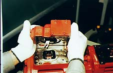
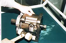
3.3.3
Remove the hexagon socket
headed bolts and remove regulator
from front pump.
a. Similarly, remove the regulator from
rear pump.
3.3.4. Loosen hexagon socket head bolts
(401) which tighten the swash plate
support (251), pump casing (271)
and valve block (312).
a.
If a gear pump or is fitted to the rear surface of the pump, then remove it
before working on the pump unit.
b.
Repeat this sequence for both the front and rear pumps.
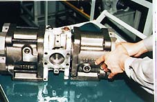
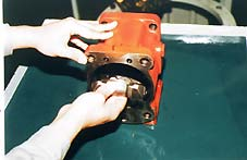
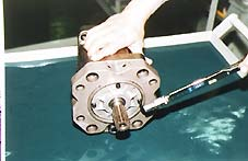
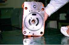
3.3.5.
Place pump horizontally on the
workbench with its regulator
mounting surface face down.
Remove the hexagon socket head
bolts (401) and separate the pump
casing (271) from it’s valve block
(312).
a
Before lowering this surface onto
the bench, spread the rubber sheet
on to the work bench so as to
prevent this surface from being damaged.
b.
Repeat this sequence for both the rear and front pumps.
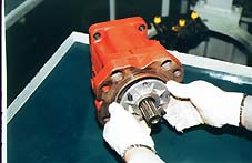
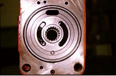
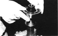
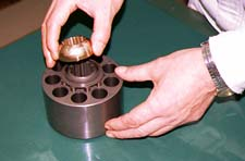
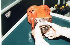
3.3.6.
Lift the cylinder (141) out of the
pump casing (271) straight over the
drive shaft (111). Additionally
extract the pistons (151), set plate
(153), spherical bush (156) and
cylinder springs (157)
simultaneously.
a.
Take care not to damage any of the
sliding surfaces of the cylinder,
spherical bush, shoes, swash plate, etc.
b.
Repeat this sequence for both the rear and front pumps.
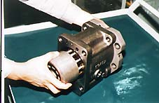
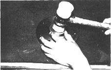
3.3.7.
Remove the hexagon socket head
bolts (406) and remove the seal cover (Front) (261).
a.
By fitting a bolt into the “pulling-out”
tapped hole of the seal cover, will
easily remove it.
b.
Take care not to damage the oil
shaft seal installed in the cover.
Similarly for the rear pump, remove the hexagon socket headed bolts on
rear pump, and remove it’s seal cover (Rear) (261) and rear cover (262).
IF a gear pump is fitted, remove this first.
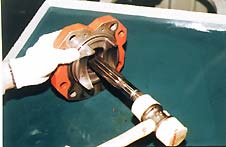
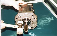
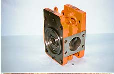
3.3.8. By tapping lightly on the flange
section of the swash plate support
(251) where it interfaces with the
pump casing side, separate the
swash plate support from it’s pump
casing.
a.
Remove the drive shaft
simultaneously with it’s swash plate support.
b.
Repeat this sequence for both the rear and front pumps.
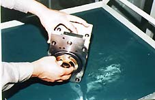
3.3.9.
Remove the shoe plate (211) and
swash plate (212) from the pump casing (271).
a.
Repeat this sequence for both the
rear and front pumps.
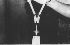
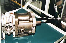
3.3.10. Tapping lightly on the external shaft
end of drive shafts (111, 113) with
plastic hammer, extract each drive
shaft from it’s swash plate support.
If required, extract the rolling
bearing (123), bearing spacer (127),
and snap ring (824) from the drive shaft (111,113).
a.
Repeat this sequence for both the
rear and front pumps.
b.
Don't reuse the bearings that you have extracted.
3.3.11.
Remove the valve plates (313, 314)
from the valve block (312).
a.
These may be removed during
sequence 5.
If required, execute sequence 12 and 13.
3.3.12.
Remove the stopper (L)(534), stopper (S)(535), servo piston (532) and tilting
pin (531) from pump casing (271).
a.
In removing the tilting pin, use a protection shield to prevent the pin head
from being damaged.
b.
Loctite has been applied in production to the fitting areas of the tilting pin
and servo piston, so care must be taken to prevent servo piston damage.
3.3.13. Remove the needle bearing (124)
and spline coupling (114) from the valve block (312).
a.
Don't remove the needle bearing
unless it definitely requiresreplacement.
b.
Don't loosen the hexagon stroke
adjustment nuts of valve block or
swash plate support. If loosened,
the flow setting will be changed
---------------------------------------------------------------------------------------------------------
3.4. Assembly Procedure
3.4.1.
Fit the servo piston (532), tilting pin (531), stopper (L)(534) and stopper
(S)(535) to the pump casing (271).
a.
In tightening the servo piston and tilting pin to the pump casing, use a
protector to prevent the tilting pin head and feedback pin from being
damaged.
b.
Apply loctite (medium) to the
threaded section of tilting pin and
servo piston and allow to set.
3.4.2.
Fit the swash plate support (251) to
it’s pump casing (271), by tapping
the former lightly with a hammer.
a.
Repeat this sequence for both the
rear and front pumps.
3.4.3.
Place pump casing with its
regulator-fitting surface down on the
bench. Fit the tilting bush of the
swash plate to it’s tilting pin (531),
and then fit the swash plate (212) to
it’s swash plate support (251)
correctly. Simultaneously fit the O-ring.
a.
Confirm with ones fingers that the
swash plate is bedded down correctly by ensuring that it could be removed
smoothly.
b.
Apply grease to the sliding sections
of the swash plate and swash plate
support, and then smoothly fit the
drive shaft through it.
c.
Repeat this sequence for both the
rear and front pumps.
In the case that one has
disassembled the roller bearings
then sequence 4 and 5 should be followed.
3.4.4.
Install the bearing spacer (127) on
to the drive shaft (111,113), and
then next install the roller bearing
(123) to this drive shaft.
3.4.5
Install the snap ring (824) onto the
drive shaft (111,113).
3.4.6.
Fit the drive shaft assembly
(complete with bearing (123),
bearing spacer (127) and snap ring
(824)) to it’s swash plate support (251).
a.
Do not tap the drive shaft with a
hammer as damage may occur.
b.
Assemble the shaft assembly into
it’s support by tapping the outer
race of bearing lightly with plastic
hammer. Fit them fully, using steel bar or so on.
c.
Repeat this sequence for both the rear and front pumps.
In the case that an oil seal has
been replaced follow sequence
3.4.7.
Install the new oil seal (774) into the
seal cover (F)(261) and seal cover ((R)(263).
3.4.8.
Assemble the front seal cover
(F)(261) into the pump casing (271)
and fix it with the hexagon socket
head bolts (406). Similarly,
assemble the rear seal cover
(R)(261) or rear cover (263) into
pump casing (271) and fix it with
hexagon socket head bolts.
a.
Apply grease lightly to the oil seal
within the seal cover.
b.
Assemble them carefully, taking full care not to damage the oil seal.
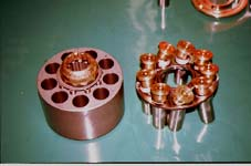
3.4.9. Install the cylinder springs (157), spacer
(158) and spherical bush (156) onto the
cylinder (141). Fit the pistons (151) and
shoe (152) through the set plate (153).
a.
Repeat this sequence for both the
rear and front pumps.
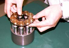
3.4.10
Assemble the piston shoe
(151,152) and set plate (153) group
onto and into the cylinder bores of
the cylinder (141), springs (157),
spherical bush (156) and spacer (158) group.
a.
Repeat this sequence for both the
rear and front pump
3.4.11.
Fit the splined phases of the
retainer and cylinder sub-assembly
into the pump casing.
a.
Repeat this sequence for both the
rear and front pumps.
b.
If the needle bearing has been
replaced then follow sequence 12.
3.3.12 2
Install the needle bearing (124) and
splined coupling (114) into the
valve block (312).

3.4.13.
Fit the valve plate (313) on to the
valve block (312), utilising the
location pin.
a.
Take care not to the mistake the
suction and delivery directions of
the valve plate.
3.4.14.
Fit the valve block (312) to it’s p
casing (271) , and tighten the
hexagon socket headed bolts (401).
Simultaneously install the O-Ring.
a.
Repeat this sequence for both the
rear and front pumps.
b.
It is easiest to assemble the rear
pump first.
c.
Take care not to mistake the Valve plate / Valve Block direction of rotation.
NOTE: For clockwise rotation (viewed from input shaft side)
Fit the valve block with the regulator up and with the delivery flange
left, when viewed from shaft end.
NOTE: For counterclockwise rotation (viewed from input shaft side)
Fit the valve block with the regulator up and with the delivery flange
on the right side, when viewed from the shaft end.
3.4.14.
Place the feedback pin of tilting pin
into the feedback lever of regulator.
Then fit the regulator and tighten
the hexagon socket head bolts.
a.
Take care not to mistake the
regulator of the front pump for that
of the rear pump.
3.4.15.
Fit the drain port plug (468).
a.
Repeat this sequence for both the rear and front pumps.
This concludes the reassembly procedure.
Source Download(PDF)